Negative vs. Positive Pressure: Hose Reel Design
October 15, 2026 | Industrial Hose Reels
Industrial hose reels are widely used for conveying liquid, gas, air and other media, and is used to connect different equipment and working areas. Although the positive pressure conveying system and vacuum suction system may use similar hoses and hose reels, their operating requirements are not the same. Hose reels specially designed for pressure conveying cannot be automatically recognized as suitable for suction conditions.
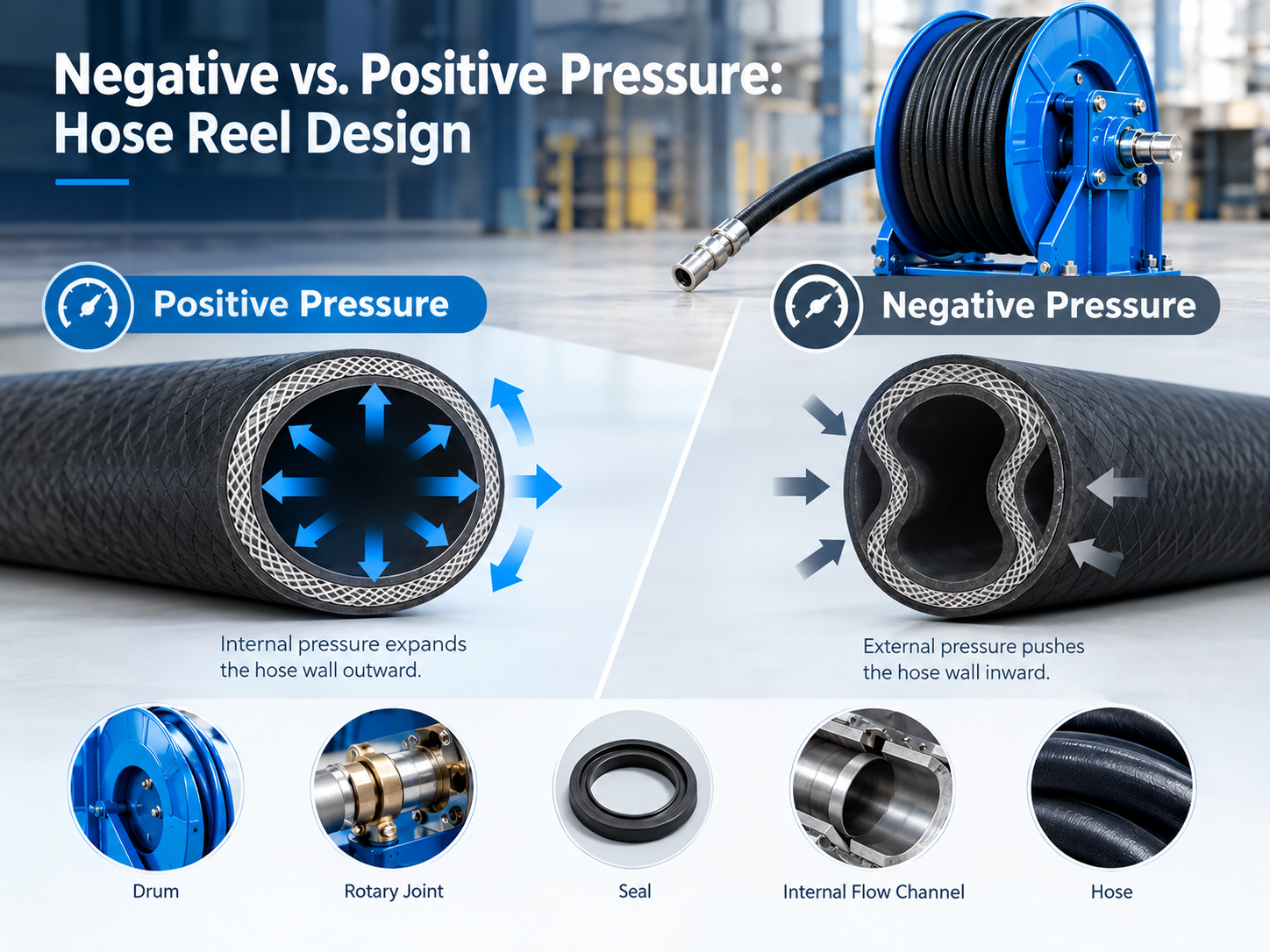
Under the condition of positive pressure, the pressure inside the hose usually expands the pipe wall outward. However, under negative pressure, the internal pressure of the hose is lower than the surrounding atmospheric pressure, and the pressure difference may cause the pipe wall to collapse inward. If the hose can’t resist this external pressure, its cross section may be deformed, restricting the flow of media and affecting the performance of the system.
The hose itself is only a part of the whole system. The arrangement of internal flow channels, rotary joints, seals, joints and hoses of the reel may affect the suction performance. Therefore, these factors need to be considered comprehensively when evaluating whether the hose reel assembly can run reliably under negative pressure.
Why Can a Hose with Positive Pressure Rating Still Fail Under Negative Pressure?
Positive Pressure and Negative Pressure Produce Different Forces
Positive pressure and negative pressure will make the hose bear different pressure. When the fluid is transported under positive pressure, the internal pressure tends to expand the pipe wall outward. The reinforcing layer can help the hose bear this load and keep its structural shape.
In the suction system, the internal pressure of the hose is lower than the external atmospheric pressure. The resulting pressure difference will form an inward force on the pipe wall. If the hose structure lacks sufficient deformation resistance, the pipe wall may buckle or flatten the cross section of the hose.
This explains why hoses with higher working pressure ratings may still perform poorly under vacuum conditions. Its reinforcement structure may be mainly used to resist internal pressure, not external pressure. Both involve the ability to withstand pressure, but they cannot replace each other.
The severity of hose deformation depends on the pressure difference between the two sides of the pipe wall, hose structure, diameter, working temperature and installation method. Some hoses can work normally when they are kept straight, but they may be deformed more easily when they are bent sharply or repeatedly.
How Does the Structure of Hose Affect the Anti-Collapse Ability?
The anti-collapse ability of the hose depends not only on the material or nominal wall thickness, but also on its internal structure, which determines whether the hose can maintain a smooth flow channel when the internal pressure is lower than the external pressure.
The reinforcement layer can improve the structural stability, but its layout is as important as its mechanical properties. Fiber reinforced layer, embedded steel wire and other structural support forms play different roles in different hose designs. Some suction hoses use spiral steel wires or similar supporting structures to help the pipe wall resist external pressure and prevent the hose from collapsing.
Material stiffness will also affect performance. A soft hose may be easier to operate, but excessive flexibility does not mean that it has enough anti-collapse ability. Temperature change may further change the material properties, and aging, wear and repeated bending may also weaken the hose’s ability to maintain its original shape.
When the hose begins to collapse, its effective cross-sectional area will decrease and the flow resistance will increase. As a result, the pumping system may have decreased flow, prolonged delivery time, unstable operation, or higher performance requirements for vacuum sources. In severe cases, the hose may even be temporarily blocked or permanently deformed.
Repeated deformation may also damage the reinforcement layer and accelerate hose wear. Therefore, the hose must have the rated performance suitable for the expected negative pressure condition, and can not be selected only according to its positive pressure level.
Which Parts of the Hose Reel Will Affect the Suction Performance?
Even if the hose has sufficient anti-collapse ability, the reel assembly may still introduce flow restriction or air leakage. Therefore, it is necessary to evaluate the internal flow channel, rotary joint, seal and hose arrangement of the reel as an integral part of the same flow system.
Internal Flow Channel and Pressure Loss
The internal flow channel connects the hose with the supply system or the collection system. If the size of the flow passage is obviously smaller than the effective inner diameter of the hose, local throttling may be formed. Sudden changes in pipe diameter, sharp turns and poorly matched connectors may also increase the loss of flow pressure.
Under pumping conditions, these losses will reduce the effective pressure difference used to promote the flow of media. Even if the vacuum source can still generate the expected negative pressure at its inlet, the pressure and flow conditions at the end of the hose may be different considering the loss in the whole flow path.
The channel diameter is not the only factor that determines the performance. Internal geometry, flow rate, medium characteristics and the number of restriction points will also affect the actual performance. Therefore, increasing the size of the hose or reel may not necessarily solve the suction problem, especially if the internal passage of the rotary joint is too narrow or there are still other restrictions in the system.
When evaluating reels, the effective flow areas of inlets, rotary joints, outlets and connectors should be compared. If the manufacturer provides relevant flow or pressure loss data, it should also confirm whether the working conditions corresponding to these data are consistent with the actual application.
Rotating Joint and Sealing Performance
The rotary joint allows the hose reel to maintain the fluid connection between the fixed part and the rotating part when rotating. In the suction application, the rotary joint not only needs to provide an appropriate flow channel, but also must maintain sufficient sealing performance under the expected negative pressure.
Equipped with rotary joints does not mean that the reel automatically has vacuum applicability. Its internal channel size, sealing structure, material, working temperature and allowable pressure range need to be verified according to practical application.
Just because a certain sealing structure performs well in positive pressure transportation does not mean that it can achieve the same sealing effect under negative pressure. According to the specific design, if the sealing performance is insufficient, ambient air may enter the system. This will reduce the vacuum available at the end of the hose and affect the stability of the suction process.
The same requirements apply to joints, adapters, valves and other connecting parts. Because air entering the system does not necessarily cause visible liquid leakage, related problems may be difficult to find through visual inspection. When confirming the applicability of the whole assembly, appropriate leak detection methods should be adopted and the manufacturer’s instructions should be followed.
Drum Diameter, Hose Bending and Arrangement Mode
The reel drum will affect the bending state of the hose during storage and use. If the diameter of the drum is too small relative to the requirements of the hose, the bending may exceed the allowable bending range of the hose or cause local deformation.
Under negative pressure, if the anti-collapse ability of the hose itself is insufficient, too small bending radius may make the problem more obvious. Even if the straight part of the hose remains stable, the bending position may be flattened or the flow passage may be limited. Repeated retraction of the hose may also cause additional mechanical stress in these areas.
Therefore, it is necessary to refer to the minimum bending radius specified by the hose manufacturer and confirm that the drum can meet the requirements in the whole operating range of the hose, not just when the hose is completely pulled out.
Hose layout should also be checked for bending, twisting, squeezing contact with surrounding equipment, or other obstacles near the reel. Whether the hose is pulled out, wound or recovered, it should maintain sufficient circulation cross section.
Therefore, it is necessary to consider the effective flow channel of the hose in the state of storage and deployment at the same time. Just because a system works well when the hose is completely pulled out does not mean that the hose can maintain the same suction performance when it is wound on the drum.
How to Confirm That the Hose Reel Is Suitable for Negative Pressure?
The applicability of negative pressure should be confirmed by the technical parameters and operating conditions of the whole assembly, and can not be inferred only by the pressure grade of a certain component. The following checks help identify potential problems before the system is put into use.
Confirm the Vacuum Rating Parameters of the Hose
First, consult the technical data provided by the hose manufacturer to confirm whether the vacuum rating, allowable negative pressure or allowable vacuum under specific conditions are indicated.
This parameter should be suitable for the actual working temperature, conveying medium, hose diameter and installation method. If the manufacturer uses the maximum vacuum degree or percentage of atmospheric pressure to indicate the rating, it should confirm its specific definition and measurement method.
Do not regard the positive working pressure rating as proof that the hose has the corresponding vacuum applicability. If the existing technical data can’t confirm that the hose is suitable for suction conditions, you should get a clear answer from the manufacturer before using it.
Check the Reel and Rotary Joint
Consult the technical documents of the hose reel manufacturer to confirm the allowable operating conditions of the whole reel assembly. It is necessary to verify whether the internal flow channels, rotary joints, seals and connecting parts have been designed or clearly defined and can be used for the expected negative pressure conditions.
Some reels may have a clear positive working pressure class, but the vacuum applicability is not indicated. In this case, the positive pressure rating alone is not enough to prove that the reel is suitable for suction application.
In particular, we need to pay attention to the internal diameter, sealing structure, material compatibility and working limitations of rotary joints. If the manufacturer provides flow data, it should compare the corresponding working conditions with the required flow and expected pressure loss of the system.
If the manufacturer does not specify whether the reel is suitable for negative pressure conditions, it should take the initiative to obtain technical confirmation, instead of default that ordinary industrial hose reels can meet the requirements.
Evaluate the Matching of the Whole System
A suction system may include hoses, reels, rotary joints, connectors, valves, filters, collection equipment and vacuum sources. All components must match the expected working conditions.
The actual operation ability of the whole system may be limited by the weakest components. For example, even if the hose has a vacuum rating, the system may not be applicable if there is air leakage at the rotary joint of the reel, or if the internal passage produces excessive flow resistance. Similarly, the suitable reel can not make up for the problem that the hose is easy to collapse under the required negative pressure.
The maximum expected pressure difference, working temperature, conveying medium, required flow rate, and the position and bending state of the hose should be considered in the evaluation. At the same time, normal operation and foreseeable changes in working conditions should also be considered, including changes in flow demand and hose layout adjustment.
If necessary, it should be confirmed to the relevant manufacturers whether these components can be used together under the specified conditions.
Verify the Performance Under Representative Working Conditions
Technical data can help to determine the expected working range of the equipment, and appropriate tests can help to confirm whether the assembled system meets the expected performance.
The verification procedure shall follow the instructions of the equipment manufacturer and the applicable safety requirements. Depending on the specific application, the test can include checking the air leakage, monitoring the vacuum degree and flow rate at the appropriate measuring position, and observing whether the hose is deformed during operation.
The test shall cover representative hose positions, including bending and winding states that may occur during normal use. The reading at the vacuum source is stable, which does not necessarily prove that there is enough flow at the end of the hose, so it needs to be judged by combining the pressure and flow measurement results.
All test conditions must be within the allowable working range of each component. Do not intentionally exceed the rated limit of hose or reel to test whether it will collapse or leak.
Common Design and Installation Errors
The following errors may still affect the pumping performance even if each component looks satisfactory.
Take positive pressure rating as proof of vacuum applicability. Hoses or reels specially designed for internal pressure may not be able to withstand external pressure under pumping conditions. The corresponding vacuum rating parameters shall be confirmed separately.
Ignore the minimum bending radius. Too small a bend may limit the flow and increase the risk of deformation of the hose. The hose arrangement and drum diameter should be checked according to the manufacturer’s requirements.
Check only hoses, ignoring rotary joints and seals. Air may enter the system through rotating joints or joints, thus reducing the available vacuum. The entire flow path must be checked.
It is considered that the larger the reel size, the better the suction performance. In some cases, it may be helpful to increase the diameter of the reel or hose, but there is no guarantee to solve the loss caused by limited internal passage, air leakage or hose collapse.
Ignore the influence of temperature and service life. Temperature change, aging, wear and repeated bending may change the flexibility and structural performance of the hose. Therefore, whether the original rated parameters are still applicable should be evaluated in combination with the actual working conditions.
Only check the condition when the hose is completely pulled out. When the hose is wound on the drum or bypassed by obstacles, its performance may be different. The verification process should reflect the layout state in actual use as much as possible.
Conclusion
Positive pressure transportation and vacuum suction will put forward different mechanical requirements for hose system. Internal pressure usually causes the hose to expand outward, while partial vacuum will produce inward pressure load, which may lead to the collapse of the hose with insufficient support capacity. Therefore, the positive pressure rating is not enough to prove that the hose is suitable for negative pressure.
Reliable suction performance also depends on the internal flow channel, rotary joint, seal, connecting parts, drum diameter and hose arrangement of hose reel. Flow restriction may reduce the available flow, while air leakage may make the system unable to maintain the required vacuum degree.
Before using the hose reel for suction application, the vacuum rating parameters of the hose should be confirmed, the allowable working conditions of the reel assembly should be verified, and the whole system should be evaluated under representative working conditions.
A reliable vacuum system depends on the correct matching and cooperation between various components, rather than simply connecting a hose with a positive pressure rating to an industrial hose reel.
Related Posts

Marine Hose Reel Selection Guide
July 10, 2026